18 Becoming familiar with the Revit Interface
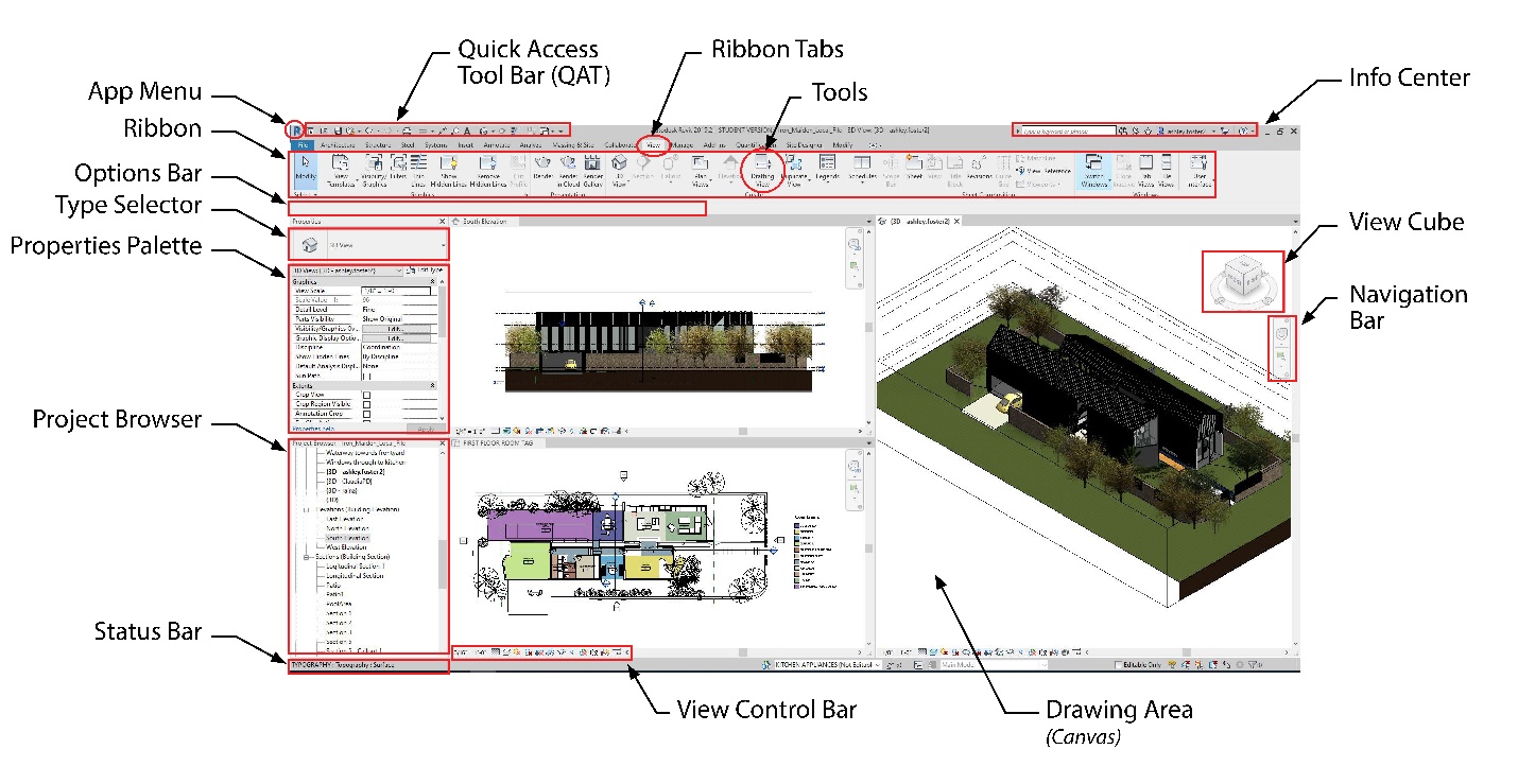
Figure 1.2 Revit Interface
|
Tab |
organize the tools based on a main function such as Architecture, Views and Massing. |
|
Ribbon |
provides tools to create elements or components of a project or family along with other commands. |
|
Tools |
are the individual icons available to initiate a command. |
|
Options Bar |
displays options available through the selected tool or element. |
|
Type Selector |
identifies the currently selected family type and provides a drop-down menu from which a different type can be chosen such as a wall or roof material or construction. |
|
Properties Palette |
is used to view or modify the parameters that define the properties of elements or canvas. |
|
Project Browser |
provides access and organizes the views, schedules, and sheets of the project. |
|
Status Bar |
provides tips or hints on what to do with the selected element or component. |
|
Info Center |
provides searchable help options and the app store icon. |
|
View Cube |
available in 3D View, adjusts the view settings. |
|
Navigation Bar |
available in 3D and 2D, adjusts zoom and view settings. |
|
View Control Bar |
quick access functions that affect the current view. |
Accessing Interface Components
- Above the ribbon, click the View tab
- Click the User Interface icon <Insert>
- One at a time uncheck and check each box to become familiar with the components. For help, reference Figure 1.3
<Insert>
Figure 1.3 Customizing the User Interface
Opening the Ribbon
- Above the ribbon, to the right of the tabs, click the icon <Insert> as shown in Figure 1.4
- Option 1: Click the drop-down arrow and click the option individually
- Option 2: Click the icon to cycle through the options
<Insert>
Figure 1.4 Ribbon display options
Opening the Properties Palette
- There are two ways of accessing the Properties Palette
- Option 1: shown in Figure 1.3
- Click the View tab
- Click the User Interface icon <Insert>
- Click Properties Palette
- Option 2: shown in Figure 1.5
- Right-click on the canvas
- Click Properties Palette
Figure 1.5 Accessing the Properties Palette
Opening the Project Browser
- There are two ways of accessing the Project Browser
- Option 1: shown in Figure 1.3
- Click the View tab
- Click the User Interface icon <Insert>
- Click Properties Palette
- Option 2: shown in Figure 1.6
- Right-click on the canvas
- Click Browsers
- Click Properties Palette
<Insert>
Figure 1.6 Accessing the Project Browser
Project Browser
Open Views
- Open the following views from the Project Browser by double-clicking the name as shown in Figure 1.7
- Floor Plan: Level 1
- 3D views: {3D}
- Elevation: West
- Schedule: Planting Schedule
- Sheet: A101 – Site Plan
<Insert>
Figure 1.7 Opening views from the Project Browser
Place family elements
- In the 3D view, scroll down the Project Browser to Families
- Click the + icon to expand the section
- Expand Planting
- Expand RPC Tree-Deciduous as shown in Figure 1.8
- Click and drag to place a Howthorne-25
(Tip: Press the Space bar to rotate an element)
- Place 5 more of any tree
<Insert>
Figure 1.8 Families in the Project Browser
Project Browser search bar
- Right click in the Project Browser
- Choose the option to Search
- Type Bathroom
- Toggle through the matches by clicking the Next and Previous buttons as shown in Figure 1.9
<Insert>
Figure 1.9 Project Browser Search
Properties Palette
Type Selector
- In the 3D view, select the roof
- Click the Type Selector
- Choose Warm Roof – Timber as shown in Figure 1.10
<Insert>
Figure 1.10 Type Selector: Warm Roof – Timber
Crop View
- In the West elevation view, go to the Properties Palette
- Scroll down to the Extents section
- Click to check the box next to Crop View
- Click to check the box next to Crop Region Visible
- Click and hold a blue dot <Insert> to adjust the boundary box
- Pull the blue dot over the elevation drawing and release the blue dot
<Insert>
Figure 1.11 Crop Box Extents
Section Box
- In the 3D view, go to the Properties Palette
- Scroll down to the Extents section
- Click to check the box next to Section Box
(Tip: If the Section Box does not show up, refer to the Trouble Shooting Chapter)
- Click on the Section box
- Use the double blue arrows to adjust the section box extents
- Pull in a side of the cube to cut through the building as shown in Figure 1.12
<Insert>
Figure 1.12 Section Box
Navigating the canvas
View Cube
The View Cube consists of two components; the Cube and the Compass as shown in Figure 1.13.
- The Cube is used to pivot around the 3D model using preset views by clicking the corners, edges and faces.
- Or click and hold the Cube while dragging the cursor around to pivot both horizontally and vertically.
- The Compass pivots around the 3D model without changing the view vertically. Click and hold on the compass and drag the cursor left and right
<Insert>
Figure 1.13 View Cube
Zoom
- In both 2D and 3D views, there are two methods for zooming
- Use the 2D wheel to zoom incrementally by options as shown in Figure 1.14
- Use the cursor scroll wheel to zoom in an out
<Insert>
Figure 1.14 2D Wheel
Panning
- Click the cursor scroll wheel anywhere on the canvas and hold it down
- Drag the cursor in any direction to move the around the canvas
Hidden Objects
- Select an element in either 2D or 3D
- Click the Temporary Hide/Isolate icon <Insert> from the View Control Bar
- Select one of the following
- Hide Element – will hide only the items selected
- Hide Category – will hide all items under the same category
- Click the Reveal Hidden Items icon <Insert> to see hidden elements
- Select the element to reveal
- Right-click on the canvas
- Click Unhide in View
- Click either Element or Category
- Click the Reveal Hidden Items icon <Insert> to close the reveal
Detail Level
- Click the Detail Level icon <Insert> on the View Control Bar to change the level of detail between Coarse, Medium and Fine
Visual Style
- Click the Visual Style icon <Insert> on the View Control Bar to change the project view between Wireframe, Hidden Line, Shaded, Consistent Colors, Realistic or Ray Trace.
Keyboard Shortcuts
Default Keyboard Shortcuts
|
Command |
|
|
MV |
Move |
|
CO or CC |
Copy |
|
RO |
Rotate |
|
DE |
Delete |
|
SL |
Split Element |
|
SF |
Split Surface |
|
RE |
Scale |
|
GR |
Group |
|
FG |
Finish group |
|
SA |
Selects all instances in project |
|
AR |
Array |
|
RP |
Reference Plane |
|
LL |
Level |
|
ML |
Model Line |
|
TX |
Text |
|
PN |
Pins/locks element in place |
|
UP |
Unpins/unlocks elements |
|
MM |
Mirror by Picking an Axis |
|
DM |
Mirror Draw Axis |
|
AL |
Align |
|
OF |
Offset |
|
VV |
Visibility Override |
|
VG |
Graphics Override |
|
CTRL + 1 |
Show or hide the properties Pane |
|
SB |
Structural Floor |
|
WA |
Initiates drawing a Wall |
|
DR |
Initiates placing a Door |
|
WN |
Initiates placing a Window |
|
CL |
Initiates placing a Column |
|
BM |
Initiates placing a Beam |
|
CM |
Initiates placing a Component |
|
TW |
Switches view to Tab View |
|
WT |
Switches view to Tile View |
Customizing Keyboard Shortcuts
Revit comes with a set of default keyboard shortcuts, but these are customizable
- Above the ribbon click the File tab
- Click Options button located in the bottom right corner of the menu
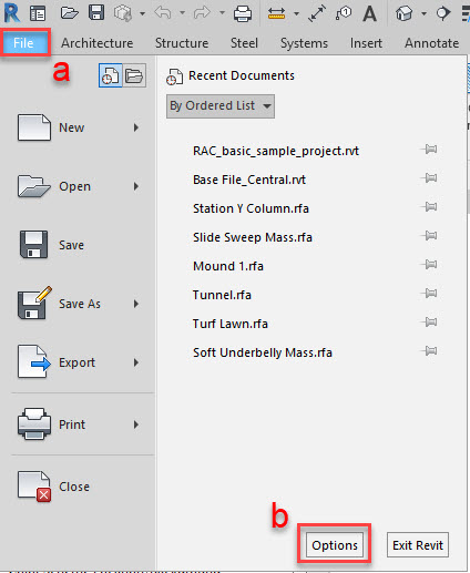
Figure 1.15 File menu
- Go to the User Interface tab along the top.
- Next to Keyboard Shortcuts click ‘Customize…’
- Select/search for the Command
- Enter the new command in the box next to Press New Keys
- Enter two characters, for example: AA
- Or enter a combination of keys, for example: CTRL + 1
- CTRL[SPACE]+[SPACE]1
- Other key commands: SHIFT, ALT
- Click Assign
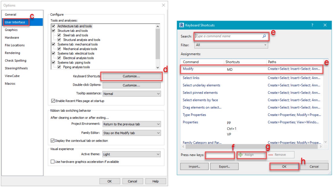 Click OK to exit
Figure 1.16 Options Menu
