Chapter 3: Design of Bicycle Facilities
Chapter Overview
This chapter starts with a discussion of the history of bike facilities in the U.S. and abroad. We describe the Highway Capacity Manual (HCM) procedure for evaluating the level of service for bicycle facilities. We then introduce students to bicycle-friendly street design principles. The concept of complete streets is discussed next. Students learn about the practices that improve the safety of bicycle facilities. Intersection design and operations tools to incorporate bicycles are introduced to the students.
Chapter Topics
- Street Design Elements for Bicycle Facility Design
- Level of Service for Bike Facilities
- Bicycle-Friendly Street Design Principles
Learning Objectives
After completing this chapter, you should be able to:
- Implement bicycle-friendly street design principles.
- Select appropriate street design elements to improve the safety and efficiency of bicycle facilities.
- Design a conventional bike lane.
- Select appropriate design elements to increase accessibility, safety, and efficiency of bicycle operation.
- Calculate the Level of Service (LOS) for bike facilities.
Bicycle Facilities
Bicycles do not have any internal combustion engines and do not use fossil fuel to operate. In addition, the production and maintenance of bicycles requires a minimum number of raw materials. Therefore, bicycles are considered a true zero-emissions mode. In terms of designing roadway facilities, the term “bicycle facilities” is not limited to the bike lanes or the bike path used. In addition to the path or space designated for bicycles, bicycle facilities include intersection control features, bikeway signing and marking, bicycle storage, and parking facilities.
In this chapter, we will first discuss the types of bicycle facilities. In particular, we will focus on the street design elements that help improve the safety and efficiency of bicycle-based operation. We will then introduce the concept of network connectivity for planning city or regional level bicycle facilities.
Types of Bicycle Facilities
Chapter 1000 of the Highway Design Manual (HDM) defines five basic types of bicycle facilities:
- Shared Roadway (No Bikeway Designation)
- Class I Bikeway (Bike Path)
- Class II Bikeway (Bike Lane)
- Class III Bikeway (Bike Route)
- Class IV Bikeway (Separated Bikeway)
Shared Roadway
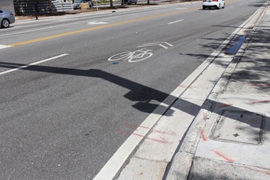
Most bicycle travel in the United States now occurs on streets and highways without bikeway designation. In some cases, shared roadway will have signs and pavement markings for bicycle operation. Most common type of pavement marking on a shared roadway is “Sharrows” as shown in Figure 3.1.
Bike Paths
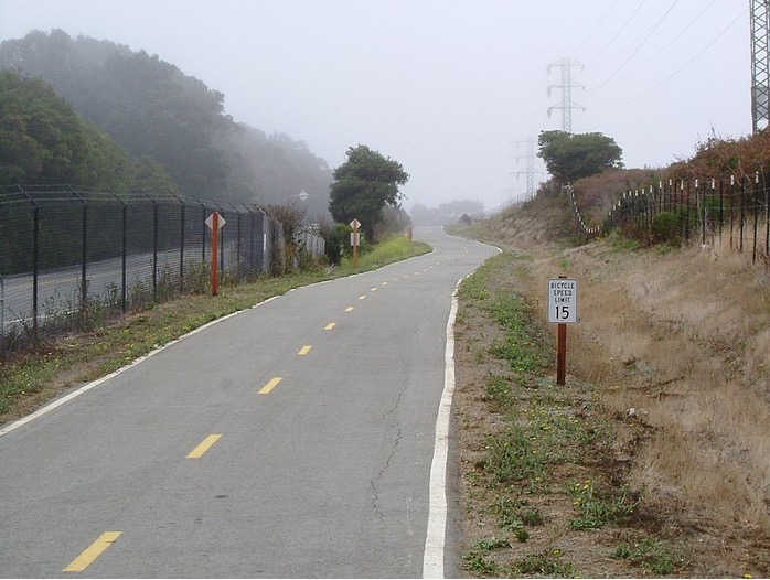
Class I bikeways or bike paths are provided to serve corridors not typically served by streets and highways. In most cases, bike paths are added for recreational purposes such as along rivers, ocean fronts, canals, utility right of way, abandoned railway right of way, within school campuses, or within and between parks. Figure 3.2 shows a bike path along California State Highway 35.
Bike Lanes
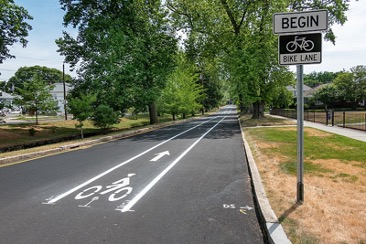
Class II bikeway or bike lanes are the most common type of bicycle facility in the United States. Bike lanes are intended to delineate the right of way assigned to bicyclists and motorists and to provide for more predictable movements by each. But a more important reason for constructing bike lanes is to better accommodate bicyclists through corridors where insufficient room exists for side-by-side sharing of existing streets by motorists and bicyclists. Figure 3.3 shows a bike lane on Pleasant Valley Parkway, Providence RI.
Bike Routes
Class III bikeway or bike routes are provided either to (a) provide continuity to other bicycle facilities (usually Class II bikeways); or (b) designate preferred routes through high demand corridors.
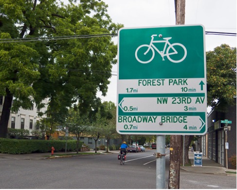
As with bike lanes, the designation of bike routes should indicate to bicyclists that there are advantages to using these routes as compared with alternative routes. This means that responsible agencies have taken actions to assure that these routes are suitable as shared routes and will be maintained in a manner consistent with the needs of bicyclists. Normally, bike routes are shared with motor vehicles. Figure 3.4 shows a wayfinding sign posted at a junction showing three different bike routes.
Separated or Class IV Bikeways
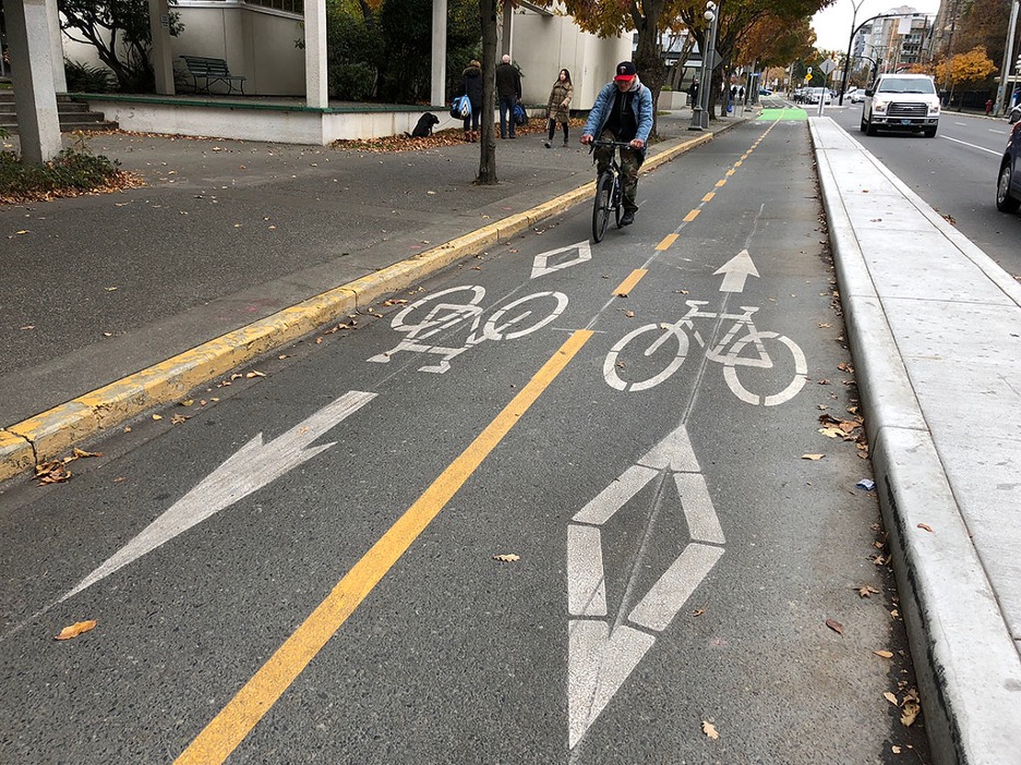
Separated bikeways are also known as cycle tracks. A cycle track is an exclusive bike facility that combines the user experience of a separated path with the on-street infrastructure of a conventional bike lane. A cycle track is physically separated from motor traffic and distinct from the sidewalk. Cycle tracks have different forms but all share common elements—they provide space that is intended to be exclusively or primarily used for bicycles, and are separated from motor vehicle travel lanes, parking lanes, and sidewalks. In situations where on-street parking is allowed cycle tracks are located to the curb side of the parking (in contrast to bike lanes). Figure 3.5 shows a two-way cycle track separated by a raised buffer between the motorized vehicle travel lane.
Bicycle Level of Service
The Highway Capacity Manual Chapter 18 provides guidelines on the method to calculate the bicycle level of service (LOS). The method includes eight main computational steps:
- Estimation of bicycle running speed
- Estimation of bicycle delay at intersection
- Finding bicycle travel speed
- Estimation of bicycle LOS score for the link
- Estimation of link LOS
- Estimation of bicycle LOS score for segment
- Finding the segment LOS letter grade using the score
Link based LOS determination is a quick approach to find the bicycle infrastructure provided in between the intersection. The segment-based LOS score includes the effect of intersection service and is more appropriate for integrated evaluation of the multimodal level of service.
Street Design Elements
The National Association of City Transportation Officials (NACTO) published Urban Street Design Guide to publish a toolbox and the tactics the cities could use to make streets safer, more livable, and more economically vibrant. In the guide, NACTO includes some guidance on several main elements of urban street:
- Lane Width – concept of “Road Diet”
- Sidewalks
- Curb Extensions
- Gateway
- Pinchpoint
- Chicane
- Bus Bulbs
- Vertical Speed Control Elements
- Transit Streets
- Storm water management
Design of Conventional Bike Lane
The NACTO Urban Bikeway Design Guide includes specific design guidelines for Class II bikeway facility. Among the different types of bike lanes, conventional bike lanes are the most common type. Below are some required guidelines for designing conventional bike lanes:
- The desirable bike lane width adjacent to a curbface is 6 feet. The desirable ridable surface adjacent to a street edge or longitudinal joint is 4 feet, with a minimum width of 3 feet. In cities where illegal parking in bike lanes is an concern, 5 foot wide bike lanes may be preferred.
- When placed adjacent to a parking lane, the desirable reach from the curb face to the edge of the bike lane (including the parking lane, bike lane, and optional buffer between them) is 14.5 feet; the absolute minimum reach is 12 feet. A bike lane next to a parking lane shall be at least 5 feet wide, unless there is a marked buffer between them. Wherever possible, minimize parking lane width in favor of increased bike lane width.
- The desirable bike lane width adjacent to a guardrail or other physical barrier is 2 feet wider than otherwise in order to provide a minimum shy distance from the barrier.
- Bicycle lane word and/or symbol and arrow markings (MUTCD Figure 9C-3) shall be used to define the bike lane and designate that portion of the street for preferential use by bicyclists.
- Bike lane word, symbol, and/or arrow markings (MUTCD Figure 9C-3) shall be placed outside of the motor vehicle tread path at intersections, driveways, and merging areas in order to minimize wear from the motor vehicle path.
- A solid white lane line marking shall be used to separate motor vehicle travel lanes from the A through bike lane shall not be positioned to the right of a right turn only lane or to the left of a left turn only lane (MUTCD 9C.04). A bike lane may be positioned to the right of a right turn only lane if split-phase signal timing is used. For additional information, see bicycle signal heads. For additional strategies for managing bikeways and right turn lanes, see through bike lanes in this guide. bike lane. Most jurisdictions use a 6 to 8 inch line.
Protected Intersection
The concept of protected intersection is discussed in the NACTO Guide Don’t Give Up at the Intersection.
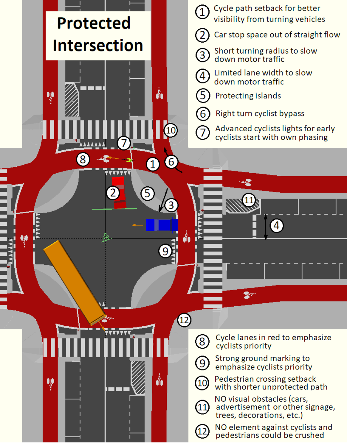
At protected intersections, the bikeway is set back from the parallel motor vehicle traffic. Unlike at conventional bike intersections, people biking are not forced to merge into mixed traffic. Instead, they are given a dedicated path through the intersection, and have the right of way over turning motor vehicles.
The setback between the motor vehicle lane and the bikeway makes people on bikes more easily visible to turning drivers than in a conventional intersection.
Corner islands anchor the design, extending the protected bike lane’s separation as far into the intersection as possible and tightening the corner’s turn radius. They create a bike queue area after the crosswalk, the natural place for people on bikes to wait.
The setback creates a waiting zone for turning cars, where drivers can yield to bikes after starting to turn but before crossing the path of oncoming bicycles. If it is large enough, this area lets drivers wait while through-traffic passes them, relieving pressure to turn too quickly.
Protected intersections also provide shorter, safer crossings for people walking. With low-speed vehicle turns and room for accessible pedestrian islands, people on foot and using personal mobility devices get many of the benefits of curb extensions.
Protected intersections create shorter, simpler crossings, more predictable movements, and better visibility between people on bikes and people driving. As a result, the intersection is more comfortable and safer for people using the bikeway and the crosswalk.
Figure 3.6 shows the important elements of a protected intersection.
Key Takeaways
- There are five types of bicycle facilities as defined by Highway Design Manual (HDM) of California Department of Transportation.
- Highway Capacity Manual provides a methodology to quantitatively measure Bicycle Level of Service (LOS).
- The NACTO Urban Street Design Guide includes design recommendations and specifications for key urban street design elements.
- Conventional bike lane design specifications are included in the NACTO Urban Bikeway Design Guide.
Self-Test
Glossary: Key Terms
Curb: A stone or concrete edging to a street or path
Bike Lane: a portion of the roadway that has been designated by striping, signage, and pavement markings for the preferential or exclusive use of bicyclists.
Bike Path: A bike path or a cycle path is a bikeway separated from motorized traffic and dedicated to cycling or shared with pedestrians or other non-motorized users.
Intersection: A point at which two or more roadway approaches intersects.
Wayfinding: A bicycle wayfinding system consists of comprehensive signing and/or pavement markings to guide bicyclists to their destinations along preferred bicycle routes.
Media Attributions
- Figure 3.1: Sharrow on US1 in West Palm Beach by Michael Rivera is under the following Creative Commons license: CC BY-SA 4.0
- Figure 3.2: Bike route along California State Highway 35 by Robert Ashworth is under the following Creative Commons license: CC BY 2.0
- Figure 3.3: Bike lane on Pleasant Valley Parkway, Providence RI by Kenneth C. Zirkel is under the following Creative Commons license: CC BY-SA 4.0
- Figure 3.4: Bike route sign with directional information by Richard Drdul is under the following Creative Commons license: CC BY-SA 2.0
- Figure 3.5: Pandora cycle track 4 by Richard Drdul is under the following Creative Commons license: CC BY-SA 2.0
- Figure 3.6: Protected intersection features by Pierre Rouzeau via Wikimedia Commons is under the following Creative Commons license: CC BY-SA 4.0
References
- AASHTO Task Force on Geometric Design (1999). AASHTO Guide for the Development of Bicycle Facilities. American Association of State Highway and Transportation Officials, Washington, DC.
- California Department of Transportation (Caltrans). (2020). Chapter 1000:– Bicycle Transportation Design, Highway Design Manual. Sacramento, CA.
- National Association of City Transportation Officials (NACTO).
- National Academies of Sciences, Engineering, and Medicine. (2022). Highway capacity manual 7th edition: A guide for multimodal mobility analysis.
A portion of the roadway that has been designated by striping, signage, and pavement markings for the preferential or exclusive use of bicyclists.
A bike path or a cycle path is a bikeway separated from motorized traffic and dedicated to cycling or shared with pedestrians or other non-motorized users.
A point at which two or more roadway approaches intersects.
A bicycle wayfinding system consists of comprehensive signing and/or pavement markings to guide bicyclists to their destinations along preferred bicycle routes.
A stone or concrete edging to a street or path

