10 Triaxial Test
Introduction
The triaxial shear test is the most versatile of all of the methods for testing the shear strength of soil and finding its cohesion (c) and angle of internal friction (φ). It can measure the total, as well as the effective stress parameters, and can be conducted on any type of soil. Drainage conditions can be controlled, and pore water pressure and volume changes can be measured accurately. The failure plane is not forced in this test, and the stress distribution of the failure plane is fairly uniform. Specimens can fail on any weak plane or can simply bulge.
The three primary triaxial tests conducted in the laboratory each allow the soil response for differing engineering applications to be observed. These are:
- Unconsolidated undrained test (UU)
- Consolidated undrained test (CU)
- Consolidated drained test (CD)
The unconsolidated undrained (UU) test is the simplest and fastest. The soil specimens are loaded, and only the total stresses are controlled and recorded. This allows determination of the undrained shear strength, cu, which is suitable for assessing the soil stability in the short-term (e.g., during or directly following a construction project). The test is generally performed on cohesive soil specimens; however, remolded sand samples can also be tested. The consolidated drained (CD) test describes the long-term loading response, and provides the strength parameters determined under effective stress control (i.e. φ and c’). It can take a significant time to complete when using cohesive soil, because the shear rate must be slow enough to allow negligible pore water pressure changes. Finally, the consolidated undrained (CU) test is the most common triaxial procedure, as it allows strength parameters to be determined based on the effective stresses (i.e., φ’ and c’) while permitting a faster rate of shearing than the CD test. This is achieved by recording the excess pore pressure change that occurs within the specimen as shearing takes place. In this manual, the basics of the UU triaxial test is covered.
Practical Application
The triaxial test, which determines the shear strength and stiffness of soil and rock, is one of the most versatile and widely performed geotechnical laboratory tests that is used in geotechnical design.
Two parameters of shear strength are required for the design of slopes and for many other analyses: calculation of the bearing capacity of any strata, and calculation of the consolidation parameters.
Objective
The objective of this experiment is
- To determine the soil strength parameters
Equipment
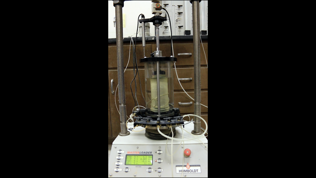
- Triaxial test setup
- Sample tubes
- Rubber ring
- Open ended cylindrical section
- Weighing balance
Standard Reference
- ASTM D4767: Standard Test Method for Consolidated Undrained Triaxial Compression Test for Cohesive Soils
Method
The general triaxial test procedure is discussed below.
Specimen & System Preparation
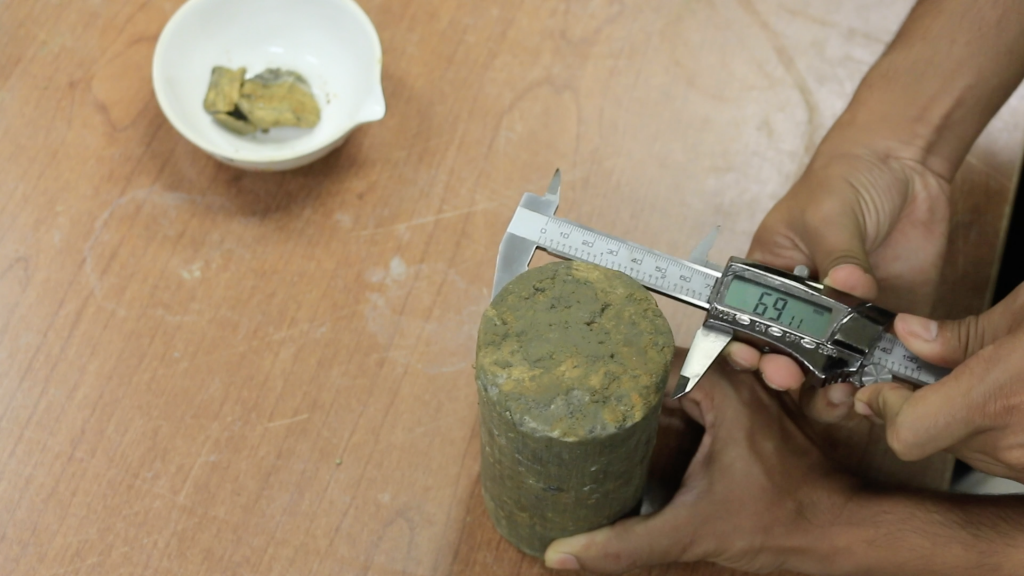
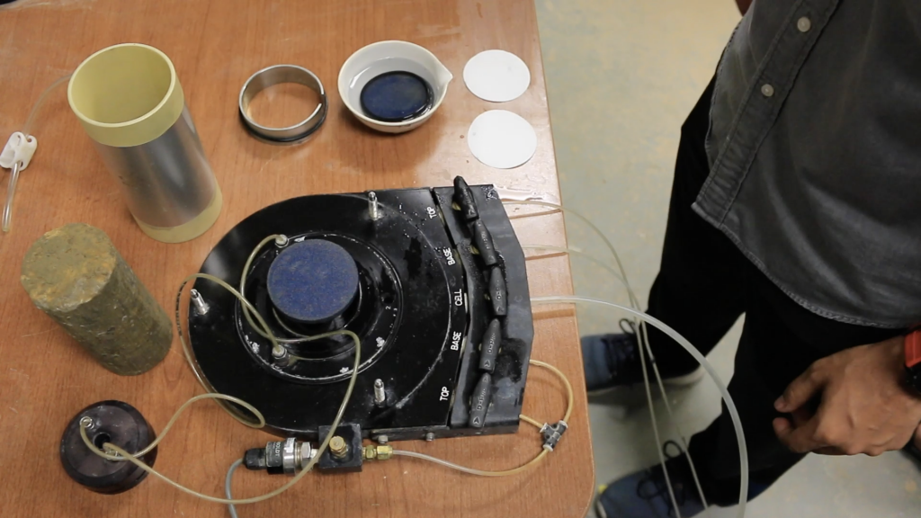
After a test specimen has been prepared from a soil sample, it is placed it into the triaxial cell. For cohesive soils, this may involve trimming undisturbed specimens extruded from Shelby tubes or cut from block samples. Granular soil specimens may require preparation directly on the pedestal, using a split-part mold. A membrane suction stretcher can be used to place the rubber membrane around the soil specimen once it is in position on the pedestal. Note that disturbance to the specimen should be kept to a minimum during the specimen preparation.
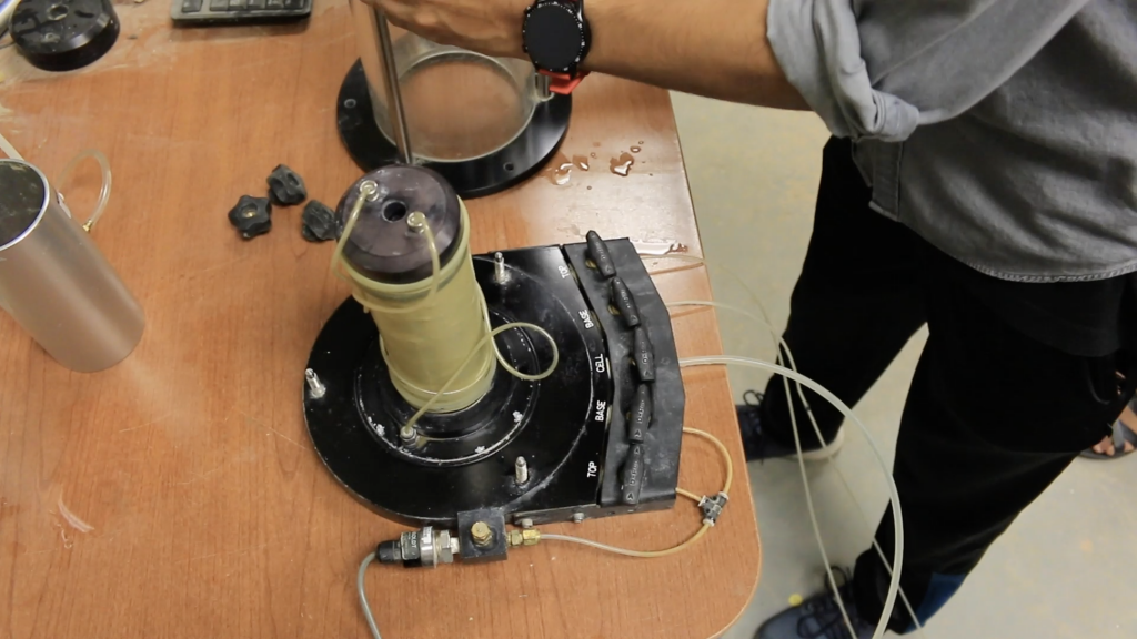
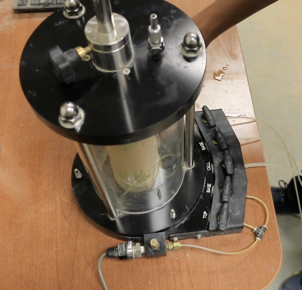
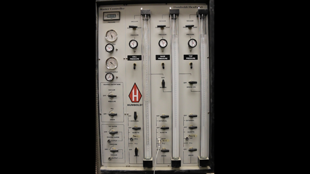
The triaxial cell other system components are assembled after placement of the specimen. During this stage, the cell is filled with fluid, the pressure/volume controllers are connected, and transducer readings are set.
Saturation
The saturation process is designed to ensure that all voids within the test specimen are filled with water, and that the pore pressure transducer and drainage lines are properly de-aired. This may be achieved by applying a partial vacuum to the specimen to remove air and draw water into the transducer and drainage lines, followed by a linear increase of the cell and back pressures. At no point should the effective stress increase above the value required for shearing, as this leads to specimen over-consolidation. To assist the specimen in reaching full saturation, the following steps may be taken:
- Use de-aired water to fill voids in the specimens.
- Increase the back pressure to force air into the solution.
Before moving to the consolidation stage, a short test is performed to determine Skempton’s B value to see whether the specimen’s degree saturation is sufficiently high. This is called a B-check and requires that the specimen drainage is closed while the cell pressure is raised by approximately 50 kPa. Note, however, that B is soil-dependent, so while a normally consolidated soft clay will produce B ≈ 1.00 at full saturation, a very dense sand or stiff clay may only show B ≈ 0.91, even if full saturation has been reached.
Consolidation
The consolidation stage is used to bring the specimen to the effective stress state required for shearing. It is typically conducted by increasing the cell pressure while maintaining a constant back pressure that is often equal to the pore pressure reached during the final saturation B-check. This process is continued until the volume change (ΔV) of the specimen is no longer significant and at least 95% of the excess pore pressure has dissipated. The consolidation response can also be used to estimate a suitable rate of strain when shearing cohesive specimens.
Shearing
The soil is sheared by applying an axial strain, εa, to the test specimen at a constant rate through upward (compression) or downward (extension) movement of the load frame platen. This rate, along with the specimen drainage condition, is dependent on the type of triaxial test being performed. Specimen response during the shear stage is typically monitored by plotting the deviator stress q or effective principal stress ratio (σ1/σ3) against the axial strain, εa. This stage is continued until a specified failure criterion has been reached, which may include identifying the peak deviator stress or peak effective principal stress ratio; observing the constant stress and excess pore pressure/volume change values; or simply reaching a specific value of axial strain.
Video Materials
Lecture Video
A PowerPoint presentation is created to understand the background and method of this experiment.
Demonstration Video
A short video is executed to demonstrate the experiment procedure and sample calculation.
Results and Discussions
A sample calculation is shown for the unconsolidated undrained triaxial test.
Calculate Axial Strain:
ε= ΔL/ L
Where,
ΔL = change in length of specimen as read from deformation indicator, mm (in.)
L0 = initial length of specimen minus any change in length prior to loading, mm (in.)
Calculate the average cross-sectional area for a given applied axial load (Ap):
Ap= Ao/(1-ε)
Determine the principal stresses at failure:
Minor principal stress (3):
σ3= Chamber pressure
Major principle stress (1):
σ1= Deviator stress at failure plus chamber pressure
Calculate the deviator stress for a given applied load: (σ1 – σ3)= P/Ap
Where,
Ap = initial average cross-sectional area of the specimen, m2(in.2)
P = given applied axial load (corrected for uplift and piston friction, if required), kPa (psi).
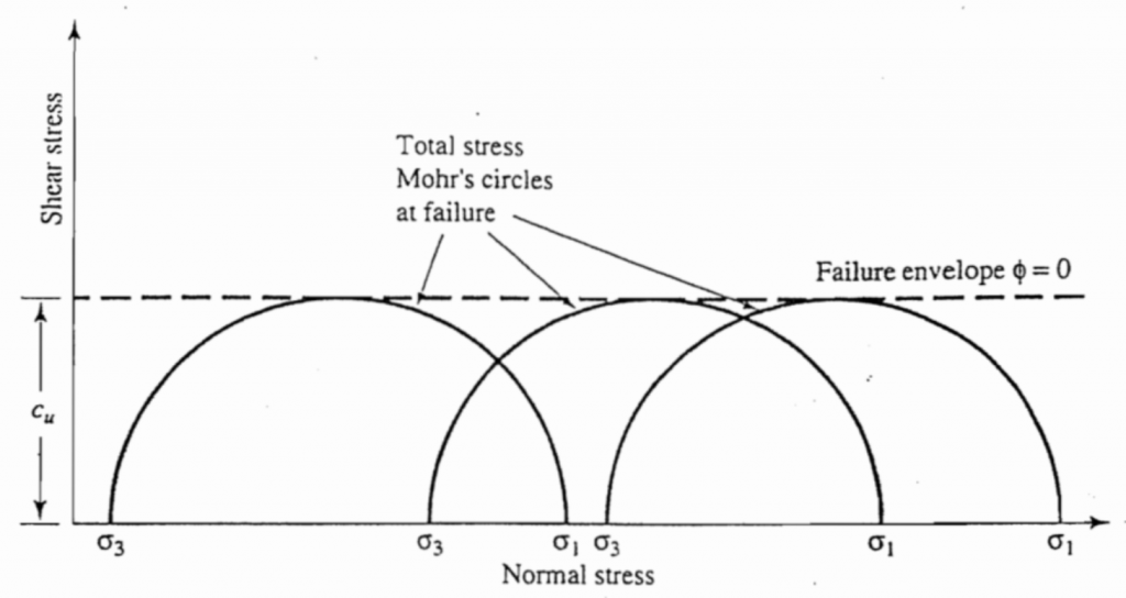
Graph the relationship between deviator stress (principal stress difference) and axial strain, plotting the deviator stress as ordinate and axial strain as abscissa. When testing a large number of samples, failure occurs when the same stresses are obtained for three or more consecutive strain readings. Graph the circle of stress as shown in Figure 10.7.
Report
Use the template provided to prepare your lab report for this experiment. Your report should include the following:
- Objective of the test
- Applications of the test
- Apparatus used
- Test procedures (optional)
- Analysis of test results – Complete the table provided and show one sample calculation.
- Summary and conclusions – Comment on the shear strength value of the soil.

