Experiment #1: Hydrostatic Pressure
1. Introduction
Hydrostatic forces are the resultant force caused by the pressure loading of a liquid acting on submerged surfaces. Calculation of the hydrostatic force and the location of the center of pressure are fundamental subjects in fluid mechanics. The center of pressure is a point on the immersed surface at which the resultant hydrostatic pressure force acts.
2. Practical Application
The location and magnitude of water pressure force acting on water-control structures, such as dams, levees, and gates, are very important to their structural design. Hydrostatic force and its line of action is also required for the design of many parts of hydraulic equipment.
3. Objective
The objectives of this experiment are twofold:
- To determine the hydrostatic force due to water acting on a partially or fully submerged surface;
- To determine, both experimentally and theoretically, the center of pressure.
4. Method
In this experiment, the hydrostatic force and center of pressure acting on a vertical surface will be determined by increasing the water depth in the apparatus water tank and by reaching an equilibrium condition between the moments acting on the balance arm of the test apparatus. The forces which create these moments are the weight applied to the balance arm and the hydrostatic force on the vertical surface.
5. Equipment
Equipment required to carry out this experiment is the following:
- Armfield F1-12 Hydrostatic Pressure Apparatus,
- A jug, and
- Calipers or rulers, for measuring the actual dimensions of the quadrant.
6. Equipment Description
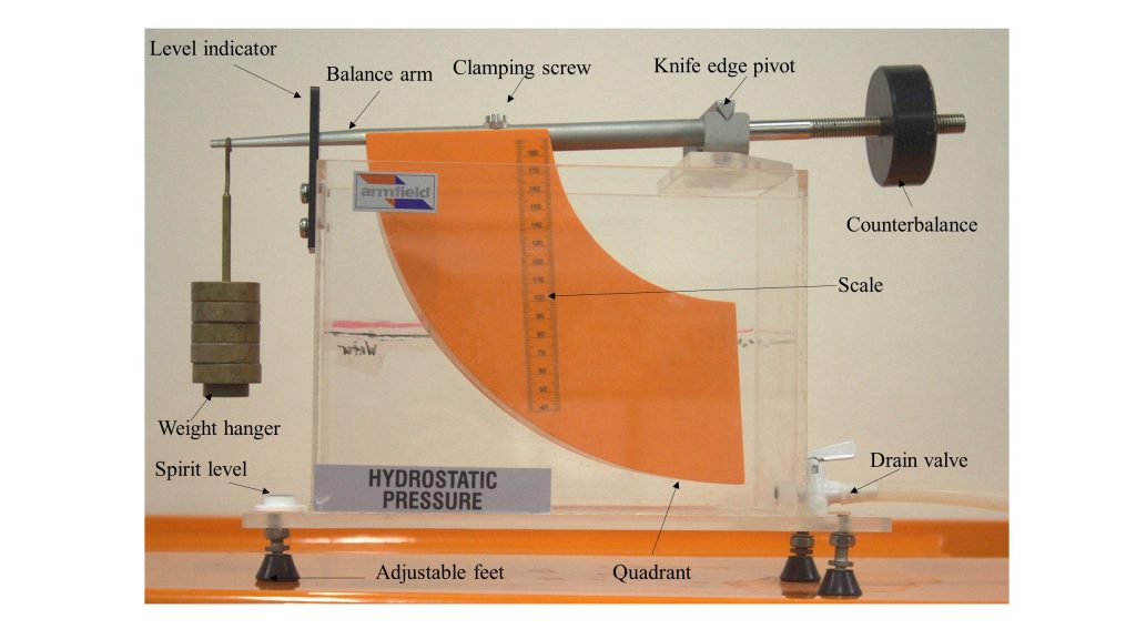
The equipment is comprised of a rectangular transparent water tank, a fabricated quadrant, a balance arm, an adjustable counter-balance weight, and a water-level measuring device (Figure 1.1).
The water tank has a drain valve at one end and three adjustable screwed-in feet on its base for leveling the apparatus. The quadrant is mounted on a balance arm that pivots on knife edges. The knife edges coincide with the center of the arc of the quadrant; therefore, the only hydrostatic force acting on the vertical surface of the quadrant creates moment about the pivot point. This moment can be counterbalanced by adding weight to the weight hanger, which is located at the left end of the balance arm, at a fixed distance from the pivot. Since the line of actions of hydrostatic forces applied on the curved surfaces passes through the pivot point, the forces have no effect on the moment. The hydrostatic force and its line of action (center of pressure) can be determined for different water depths, with the quadrant’s vertical face either partially or fully submerged.
A level indicator attached to the side of the tank shows when the balance arm is horizontal. Water is admitted to the top of the tank by a flexible tube and may be drained through a cock in the side of the tank. The water level is indicated on a scale on the side of the quadrant [1].
7. Theory
In this experiment, when the quadrant is immersed by adding water to the tank, the hydrostatic force applied to the vertical surface of the quadrant can be determined by considering the following [1]:
- The hydrostatic force at any point on the curved surfaces is normal to the surface and resolves through the pivot point because it is located at the origin of the radii. Hydrostatic forces on the upper and lower curved surfaces, therefore, have no net effect – no torque to affect the equilibrium of the assembly because the forces pass through the pivot.
- The forces on the sides of the quadrant are horizontal and cancel each other out (equal and opposite).
- The hydrostatic force on the vertical submerged face is counteracted by the balance weight. The resultant hydrostatic force on the face can, therefore, be calculated from the value of the balance weight and the depth of the water.
- The system is in equilibrium if the moments generated about the pivot points by the hydrostatic force and added weight (=mg) are equal, i.e.:

where:
m : mass on the weight hanger,
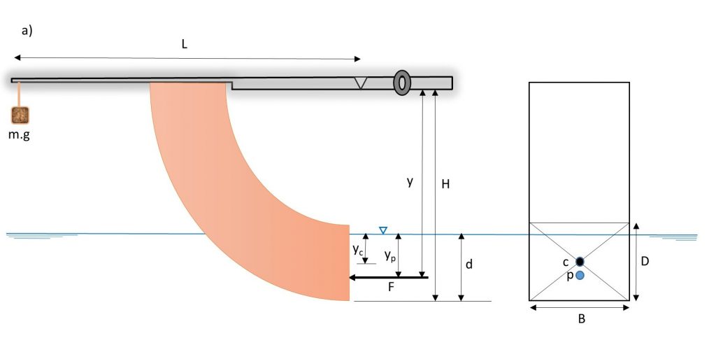
L : length of the balance arm (Figure 1.2)
F : Hydrostatic force, and
y : distance between the pivot and the center of pressure (Figure 1.2).
Then, calculated hydrostatic force and center of pressure on the vertical face of the quadrant can be compared with the experimental results.
7.1 Hydrostatic Force
The magnitude of the resultant hydrostatic force (F) applied to an immersed surface is given by:

where:
Pc : pressure at centroid of the immersed surface,
A: area of the immersed surface,
yc : centroid of the immersed surface measured from the water surface,
 : density of fluid, and
g : acceleration due to gravity.
The hydrostatic force acting on the vertical face of the quadrant can be calculated as:
- Partially immersed vertical plane (Figure 1.2a):

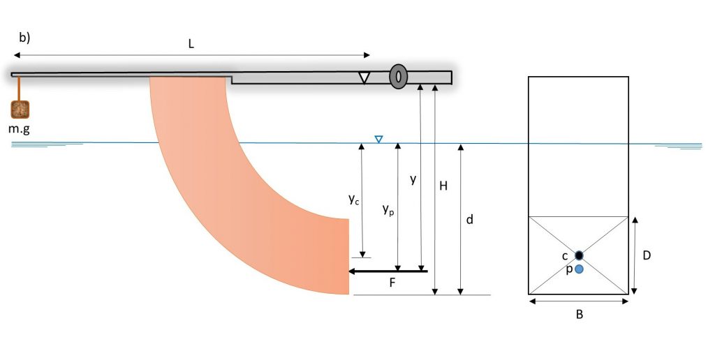
- Fully immersed vertical plane (Figure 1.2b):

where:
B : width of the quadrant face,
d : depth of water from the base of the quadrant, and
D : height of the quadrant face.
7.2 Theoretical Determination of Center of Pressure
The center of pressure is calculated as:

 is the 2nd moment of area of immersed body about an axis in the free surface. By use of the parallel axes theorem:

where  is the depth of the centroid of the immersed surface, and
  is the 2nd moment of area of immersed body about the centroidal axis. is calculated as:
- Partially immersed vertical plane:

- Fully immersed vertical plane:
![\displaystyle I_x=BD \left[ \frac{D^2}{12}+\left(d-\frac{D}{2}\right)^2 \right] \qquad (6b)](https://uta.pressbooks.pub/app/uploads/quicklatex/quicklatex.com-ce7a60a5a8f0600ec1c0f748d233db58_l3.png "Rendered by QuickLaTeX.com")
The depth of the center of pressure below the pivot point is given by:

in which H is the vertical distance between the pivot and the base of the quadrant.
Substitution of Equation (6a and 6b) and into (4) and then into (7) yields the theoretical results, as follows:
- Partially immersed vertical plane (Figure 1.2a):

- Fully immersed vertical rectangular plane (Figure 1.2b):

7.3 Experimental Determination of Center of Pressure
For equilibrium of the experimental apparatus, moments about the pivot are given by Equation (1). By substitution of the derived hydrostatic force, F from Equation (3a and b), we have:
- Partially immersed vertical plane (Figure 1.2a):

- Fully immersed vertical rectangular plane (Figure 1.2b):

8. Experimental Procedure
Begin the experiment by measuring the dimensions of the quadrant vertical endface (B and D) and the distances (H and L), and then perform the experiment by taking the following steps:
- Wipe the quadrant with a wet rag to remove surface tension and prevent air bubbles from forming.
- Place the apparatus on a level surface, and adjust the screwed-in feet until the built-in circular spirit level indicates that the base is horizontal. (The bubble should appear in the center of the spirit level.)
- Position the balance arm on the knife edges and check that the arm swings freely.
- Place the weight hanger on the end of the balance arm and level the arm, using the counter weight, so that the balance arm is horizontal.
- Add 50 grams to the weight hanger.
- Add water to the tank and allow time for the water to settle.
- Close the drain valve at the end of the tank, then slowly add water until the hydrostatic force on the end surface of the quadrant is balanced. This can be judged by aligning the base of the balance arm with the top or bottom of the central marking on the balance rest.
- Record the water height, which displayed on the side of the quadrant in mm. If the quadrant is partially submerged, record the reading in the partially submerged portion of the Raw Data Table.
- Repeat the steps, adding 50 g weight each time, until the final weight of 500 g is reached. When the quadrant is fully submerged, record the readings in the fully submerged part of the Raw Data Table.
- Repeat the procedure in reverse by progressively removing the weights.
- Release the water valve, remove the weights, and clean up any spilled water.
9. Results and Calculations
Please visit this link for accessing the excel workbook for this experiment.
9.1 Result
Record the following dimensions:
- Height of quadrant endface, D (m) =
- Width of submerged, B (m)=
- Length of balance arm, L (m)=
- Distance from base of quadrant to pivot, H (m)=
All mass and water depth readings should be recorded in the Raw Data Table:
Raw Data Table
| Test No. |
Mass, m (kg) |
Depth of Immersion, d (m) |
|
| Partially submerged | 1 | ||
| 2 | |||
| 3 | |||
| 4 | |||
| 5 | |||
| Fully Submerged | 6 | ||
| 7 | |||
| 8 | |||
| 9 | |||
| 10 | |||
9.2 Calculations
Calculate the following for the partially and fully submerged quadrants, and record them in the Result Table:
- Hydrostatic force (F)
- Theoretical depth of center of pressure below the pivot (y)
- Experimental depth of center of pressure below the pivot (y)
Result Table
| Test No. | Mass m(kg) | Depth of immersion d(m) | Hydrostatic force F(N) | Theoretical depth of center of pressure (m) | Experimental depth of center of pressure (m) |
| 1 | |||||
| 2 | |||||
| 3 | |||||
| 4 | |||||
| 5 | |||||
| 6 | |||||
| 7 | |||||
| 8 | |||||
| 9 | |||||
| 10 |
10. Report
Use the template provided to prepare your lab report for this experiment. Your report should include the following:
- Table (s) of raw data
- Table (s) of results
- Plots of the following graphs:
- Hydrostatic force (y-axis) vs depth of immersion (y-axis),
- Theoretical depth of center of pressure (y-axis) vs depth of immersion (x-axis),
- Experimental depth of center of pressure (y-axis) vs depth of immersion (x-axis),
- Theoretical depth of centre of pressure (y-axis) vs experimental depth of center of pressure (x-axis). Calculate and present value for this graph, and
- Mass (y-axis) vs depth of immersion (x-axis) on a log-log scale graph.
- Comment on the variations of hydrostatic force with depth of immersion.
- Comment on the relationship between the depth of the center of pressure and the depth of immersion.
- For both hydrostatic force and theoretical depth of center of pressure plotted vs depth of immersion, comment on what happens when the vertical endface of quadrant becomes fully submerged.
- Comment on and explain the discrepancies between the experimental and theoretical results for the center of pressure.
