Experiment #5: Impact of a Jet
1. Introduction
Moving fluid, in natural or artificial systems, may exert forces on objects in contact with it. To analyze fluid motion, a finite region of the fluid (control volume) is usually selected, and the gross effects of the flow, such as its force or torque on an object, is determined by calculating the net mass rate that flows into and out of the control volume. These forces can be determined, as in solid mechanics, by the use of Newton’s second law, or by the momentum equation. The force exerted by a jet of fluid on a flat or curve surface can be resolved by applying the momentum equation. The study of these forces is essential to the study of fluid mechanics and hydraulic machinery.
2. Practical Application
Engineers and designers use the momentum equation to accurately calculate the force that moving fluid may exert on a solid body. For example, in hydropower plants, turbines are utilized to generate electricity. Turbines rotate due to force exerted by one or more water jets that are directed tangentially onto the turbine’s vanes or buckets. The impact of the water on the vanes generates a torque on the wheel, causing it to rotate and to generate electricity.
3. Objective
The objective of this experiment is to investigate the reaction forces produced by the change in momentum of a fluid flow when a jet of water strikes a flat plate or a curved surface, and to compare the results from this experiment with the computed forces by applying the momentum equation.
4. Method
The momentum force is determined by measuring the forces produced by a jet of water impinging on solid flat and curved surfaces, which deflect the jet at different angles.
5. Equipment
The following equipment is required to perform the impact of the jet experiment:
- F1-10 hydraulics bench,
- F1-16 impacts of a jet apparatus with three flow deflectors with deflection angles of 90, 120, and 180 degrees, and
- Stopwatch for timing the flow measurement.
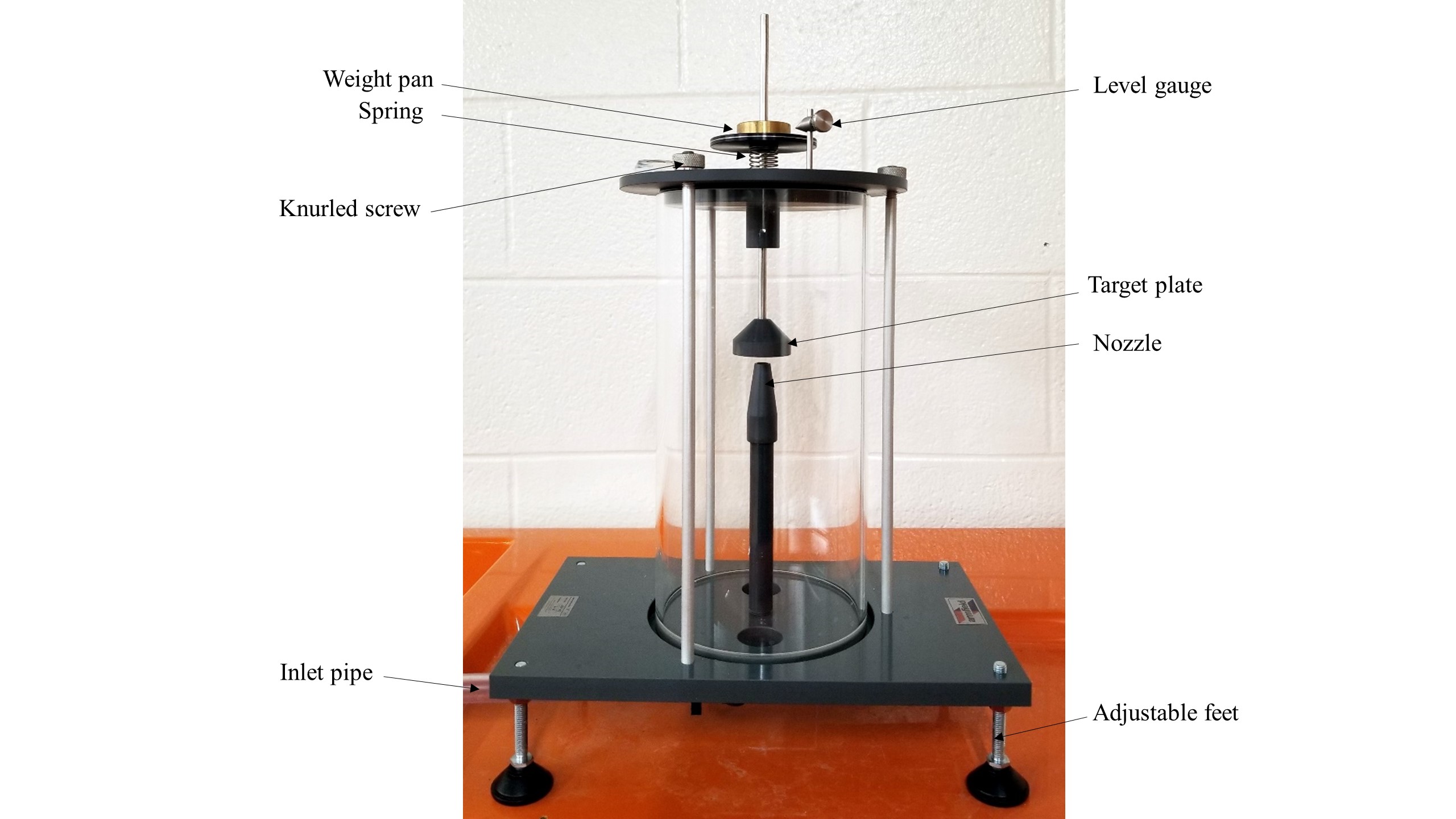
6. Equipment Description
The jet apparatus is a clear acrylic cylinder, a nozzle, and a flow deflector (Figure 5.1). Water enters vertically from the top of the cylinder, through a nozzle striking a target, mounted on a stem, and leaves through the outlet holes in the base of the cylinder. An air vent at the top of the cylinder maintains the atmospheric pressure inside the cylinder. A weight pan is mounted at the top of the stem to allow the force of the striking water to be counterbalanced by applied masses [5].
7. Theory
The velocity of the water (v) leaving the nozzle with the cross-sectional area (A) can be calculated by:

in which Q is the flow rate.
Applying the energy equation between the nozzle exit point and the surface of the deflector shows that the magnitude of the flow velocity does not change as the water flows around the deflector; only the direction of the flow changes.
Applying the momentum equation to a control volume encompassing the deflected flow results in:

where:
Fy: force exerted by the deflector on the fluid
 : fluid density
 : 180-
 , where is the flow deflection angle (Figure 5.2).
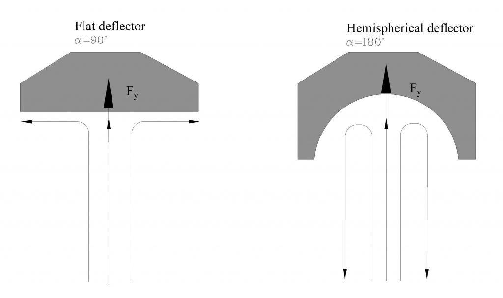
From equilibrium of forces in a vertical direction, Fy is balanced by the applied weight on the weight pan, W (W = mg, where m is the applied mass), i.e., Fy = W. Therefore:

Since Q = vA, this equation can be written as:

8. Experimental Procedure
Perform the experiment by taking the following steps:
- Remove the top plate (by releasing the knurled nuts) and the transparent cylinder from the equipment, and check and record the exit diameter of the nozzle.
- Replace the cylinder, and screw the 90-degree deflector onto the end of the shaft.
- Connect the inlet tube to the quick-release connector on the bench.
- Replace the top plate on the transparent cylinder, but do not tighten the three knurled nuts.
- Using the spirit level attached to the top plate, level the cylinder by adjusting the feet.
- Replace the three knurled nuts, then tighten in sequence until the built-in circular spirit level indicates that the top plate is horizontal. Do not overtighten the knurled nuts, as this will damage the top plate. The nuts should only be tightened enough to level the plate.
- Ensure that the vertical shaft is free to move and is supported by the spring beneath the weight pan.
- With no weights on the weight pan, adjust the height of the level gauge until it aligns with the datum line on the weight pan. Check that the position is correct by gently oscillating the pan.
- Place a mass of 50 grams on the weight pan, and turn on the pump.
- Open the bench valve slowly, and allow water to impinge upon the target until the datum line on the weight pan is level with the gauge. Leave the flow constant. Observe and note the flow behavior during the test.
- Measure the flow rate, using the volumetric tank. This is achieved by closing the ball valve and measuring the time that it takes to accumulate a known volume of fluid in the tank, as measured from the sight glass. You should collect water for at least one minute to minimize timing errors.
- Repeat this procedure by adding an additional 50 grams incrementally, until a maximum mass of 500 grams has been applied.
- Repeat the entire test for each of the other two flow deflectors.
9. Results and Calculations
Please use this link for accessing excel workbook for this experiment.
9.1. Results
Use the following tables to record your measurements.
Raw Data Table
| Test No. | Deflection Angles (degree) | ||||||||
| 90 | 120 | 180 | |||||||
| Volume (Liter) |
Time (s) |
Applied Mass (kg) |
Volume (Liter) |
Time (s) |
Applied Mass (kg) |
Volume (Liter) |
Time (s) |
Applied Mass (kg) |
|
| 1 | |||||||||
| 2 | |||||||||
| 3 | |||||||||
| 4 | |||||||||
| 5 | |||||||||
| 6 | |||||||||
| 7 | |||||||||
| 8 | |||||||||
| 9 | |||||||||
| 10 | |||||||||
9.2. Calculations
The nozzle should be of the following dimensions.
- Diameter of the nozzle: d= 0.008 m
- Cross sectional area of the nozzle: A= 5.0265×10⁻⁵ m2
These values may be measured as part of the experimental procedure and replaced with the above dimensions.
For each set of measurements, calculate the applied weight (W), flow rate (Q), velocity squared (v2), force (Fy ), and theoretical and experimental slope (S) of the relationship between W and v2. The theoretical slope is determined from Equation 5, as follows:

The experimental value of S is obtained from a graph W of plotted against v2.
Result Table
| Nozzle Diameter (m)= | Flow Area (m2) = | Deflector Angle (degree)= | |||||
| Test No. | Applied Weight (N) | Flow Rate (m3/s) | Velocity (m/s) | Velocity2 (m/s)2 | Force (N) | Theoretical Slope | Experimental Slope |
| 1 | |||||||
| 2 | |||||||
| 3 | |||||||
| 4 | |||||||
| 5 | |||||||
| 6 | |||||||
| 7 | |||||||
| 8 | |||||||
| 9 | |||||||
| 10 | |||||||
10. Report
Use the template provided to prepare your lab report for this experiment. Your report should include the following:
- Table(s) of raw data
- Table(s) of results
- Graph(s)
- Plot a graph of velocity squared, v2, (x-axis) against applied weight, W, (y-axis). Prepare one graph, presenting the results for all three deflectors, and use a linear trend line, setting the intercepts to zero, to show this relationship. Find the slopes of these lines. Record the slopes in the Results Table, as the experimental slope.
- Compare the slopes of this graph with the slopes calculated from the theoretical relationship from Equation 5.
- Plot the measured force from the weights (W) versus the force of the water on the deflector (Fy) that is calculated by using the momentum equation, i.e., Equation 2.
- Discuss your results, focusing on the following:
- Does this experiment provide a feasible means of verifying the conservation of momentum equation? Try to be quantitative in your comparison between the experimental and calculated results.
- Would the results have been different if the deflectors were closer to the nozzle? Explain.
- Comment on the agreement between your theoretical and experimental results, and give reasons for any differences.
- Comment on the significance of any experimental errors.
