Chapter 10: Details and Annotations
10.1 DETAILS
Detail Lines (Linework)
Linework is added using the same tools that are available to build elements. Line styles offer different weights and patterns such as dashed, dash-dot, etc.
Field Region
Field regions add patterns or hatches to help describe a material.
Masking Region
Masking regions either hide linework or fade linework using transparency.
Detail Component
A detail component is a profile family that is saved individually and uploaded into the project such as top and bottom plates, blocking, soldier bricks, etc.
Repeating Elements
A repeating element is a time-efficient tool used to draw a repeating detail in a linear fashion such as a regular brick, soldier bricks, grout spacing, etc.
Detail Groups
A detail group is used to draw multiple details under a single name.
10.2 ADDING 2D DETAILS
Create a Masking Region
- In the Level 1 view, click the View tab
- Click the Section icon

- Place a section cut across Office 104 and 108 as shown in Figure 10.1 (left)
- In the Project Browser, open Section 2
- Under the View tab, click the Callout icon

- Click and drag to place 4 callout bubbles as shown in Figure 10.1 (right). If the callout tag is placed over the building section, click the blue dot closest to the bubble and drag it off the building.
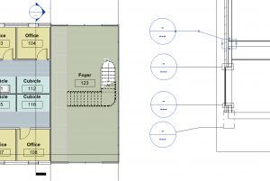
Figure 10.1 Section cut placed in Level 1 view (left) and Callouts placed in Section view (right) - In the Project Browser open Section 2 – Callout 1
- Adjust the crop box if needed by clicking and dragging the blue dots
- On the Option View Bar change the Detail Level to Fine
 and make sure the Visual style is on Hidden Line
- In the Annotate tab, click the Region drop-down arrow and click the Masking Region icon

- In the Lines Style panel, change the line to <invisible lines>
- Use the rectangle tool
 to cover the floor where it intersects the wall
 - Click the green
 checkmark to finish the mask
 - Select the mask and adjust the extents using the blue dots to match Figure 10.2
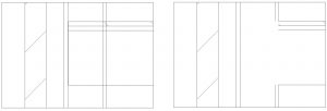
Figure 10.2 Masking region before (left) and after placement (right)
Create a Field Region
- In the Section 2 – Callout 1 view, go to the Annotation tab
- Click the Region drop-down arrow and click the Filled Region icon

- Change the Line Style to Thin Lines
- Use the Type Selector to choose the Diagonal Up pattern
- Place the same filled region for the flooring substrate under the finished floor as shown in Figure 10.3
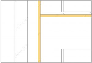
Figure 10.3 Filled regions (highlighted in yellow)
Add Detail Lines (linework) and Component Detail
- In the Section 2 – Callout 1 view, click the Detail Line icon

- Change the Line Style to Thin Lines and draw the lines as shown in Figure 10.4
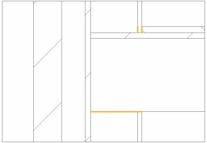
Figure 10.4 Thin lines drawn are highlighted in yellow - Continue using the Thin Line style and draw the blocking, top plates, and bottom plates. Use Figure 10.5 for reference. The actual dimensions of wood members are 1.5” thick.
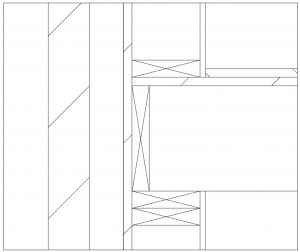
Figure 10.5 Blocking, top plates and bottom plates drawn using Detail Lines
Create a Repeating element
- In the Section 2 – Callout 1 view, draw a <invisible lined> masked region over the brick layer
- Use the Bring to Front icon
 if the region is not showing
 - Click the Component
 drop-down arrow and click the Repeating Detail Component
- Use the Type Selector to choose the Repeating Detail Brick
- Click the bottom left corner of the brick layer and drag the cursor up to place the repeating pattern as shown in Figure 10.6
- Click the Detail Lines icon
- Use the Start-End-Radius tool
 to create a grout line
 - Use the Copy tool to make multiple grout lines as shown in Figure 10.6
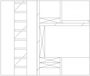
Figure 10.6 Repeat brick component over
10.3 ANNOTATIONS
Tag by material
- In the Annotate tab click the Material Tag icon

- Hover the cursor over the brick, click on the brick to place the first part of the tag, drag the cursor further to the left, and click the screen. Now the first half of the leader line is placed.
- Drag the cursor to the left one last time and place the last of the leader line
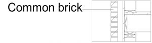
Figure 10.7 Leader line
Tag by Text
- In the Annotate tab click the Text icon

- Click the Two Segments
 icon on the Leader Panel
 - Click on the stud to place the end of the leader liner. Drag the cursor to the left and click again, drag to the left and finish placing
- A text box will appear, type 2X6 Wood Stud
TIP
If the tag is not showing, click on the crop box. Adjust the extents to the dashed box around it and pull the left side far out. - Select the Text
- In the Properties Palette use the Type Selector to choose the Text 3/32” Arial
- Click the Edit Type
- Click duplicate and accept the default name
- Next to Leader Arrowhead use the drop-down to select the Arrow Filled 15 Degree
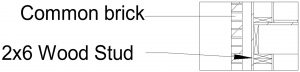
Figure 10.8 Text with leader lines pointing at their respective material level
TIP
Tag by Category
- Open the Level 1 Floorplan view
- In the Annotate tab click the Tag by Category icon

- Click on each door and window as shown in Figure 10.9
- Adjust the placements so each symbol is not on top on the plan
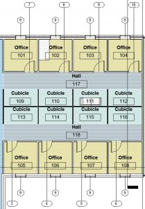
Figure 10.9 Doors and Windows Tags placed In Level 1 view
Legends and Keynote Legends
Legends
Legends are used to identify the symbols and add notes that can be added to multiple sheets during the Construction Document phase.
Keynote Legends
Keynotes are a combination of text references in a legend that provide written information about elements, materials, or codes in the Construction Document.
- In the Level 1 view click to open the View tab
- Click the Legend icon

- Name the new legend Symbols
- Choose the ¼” = 1’
- In the Project Browser, expand the Families section then expand the Annotation Symbols section
- Expand Door Tag then click and drag the Door Tag onto the canvas
- Do the same for Spot Elevation – Target Filled, Section Head – Filled, Window Tag and Wall Tag ½”
- Click on the Annotate tab then click on the Text icon
- Add a text box to the left of the symbols as shown in Figure 10.10
- Use the Type Selector to change the text to 3/32” Arial
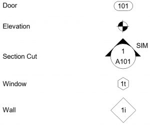
Figure 10.10 Symbol Legend
Dimensions
- Open the Level 1 view
- Click the Annotate tab
- Click the Aligned Dimension

- Hover over the west wall on of the Open Workspace
- Use the Tab key to cycle through the options and choose the exterior face, click to place the first edge
- Measure from this wall to the exterior face of glass curtain wall
- Practice placing more dimensions including the Angular, Radial and Arc Length dimensions as shown in Figure 10.11
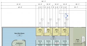
Figure 10.11 Dimension strings added to the Level 1 View
Modifying Dimensions
- Select the smaller radius dimension on conference room 119
- Click Edit Type
- Duplicate and accept the default name
- Change the following properties
- Text Size: 1/32”
- Units Format: Click the gray button
- Uncheck the Use project settings
- Change Rounding to nearest 1/8”
- Click Apply and OK
- Hover the cursor over the blue dot underneath the dimension text
- When the words Drag Text appear, click and hold the blue dot and drag it away from the leader line
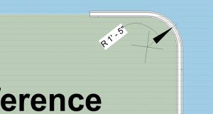
Figure 10.10 Modified radial dimension
