Chapter 8: Schematic Design and Room & Color Fill Plans
8.1 SCHEMATIC DESIGN
Import a CAD file
- In the Level 1 view, click the Insert tab
- Click the Link CAD icon

- Locate the folder and select the file
- At the bottom of the window make sure Current View only is checked
- Use the Positioning drop-down menu to select Manual – Origin
- Click Open
- Use the Measure tool
 and Scale
  if necessary
 - With the drawing selected click the Lock button

TIP
It is easiest to use a straight staircase as a reference given the tread measurements are universally about 1 foot deep.
Add the separate plan files to their Revit level respectively
Insert a 2D image
- Under the Insert tab click the Insert Image icon

- Locate the folder, select the file, and click open
- The dashed X represents the image boundary, click anywhere on the canvas to place it
- Use the Measure tool and Scale if necessary
- With the drawing selected click the Lock button
Importing a 3D
3D models can be imported into Revit from Sketch-up and FormIt, but they are imported in as a Family file that acts as guidelines to create a mass as covered in Chapters 6 and 7.
8.2 ROOM AND COLOR FILL
Set room computations
- In the Level 1 view, click the Architecture tab
- Click the Room and Area panels drop-down arrow
- Click the Area and Volume Computation
- In the window, select the Areas Only and At wall finish options
- Click OK
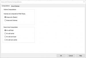
Figure 8.1 Area and Volume Computation window
Place a room individually
- In the Level 1 view, click the Architecture tab
- Under the Rooms & Area panel, click the Room icon

- On the ribbon, make sure that the Tag on Placement icon
 is highlighted in blue. Click to active and un-active the icon. Hover over a room to see the difference.
 - Click to place a room as shown in Figure 8.2
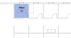
Figure 8.2 Placed room tag shown in the Level 1 view - Hover the cursor over the room tag and select the X
- In the Properties Palette change the Number to 101 and the Name to Office as shown in Figure 8.2
TIP
Changes can also be made by Double-clicking on the text box
Add and modify Separation Lines
- Click the architecture tab on the ribbon
- Click the Room Separation icon

- Draw the lines to create separate spaces as shown in Figure 8.3
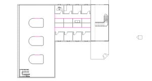
Figure 8.3 Separation Lines indicated by the pink lines - Under the Manage tab, click the Additional settings
 drop-down menu and select the Line Styles option
- Expand the Lines Category by click the + sign
- Next to the <Room Separation>, click the Line Color box
- Change the color to White and click OK
TIP
Line styles are also used to modify model lines and detail lines throughout the project
Create a schedule to place rooms
- Click the View tab
- Click the Schedules icon

- Click the Schedules/Quantities icon

- In the New Schedule window, scroll down the Category list and select the Rooms option
- Click OK
- In the Available fields, separately select Number, Name, and Area and click the Add Parameter button INSERT.
TIP
The order in which parameters are added dictates how the columns are set up in the schedule. It is important to add the parameters in order from top to bottom to how the schedule is referenced from left to right - Click OK
- On the ribbon, click the Insert Data Row until 23 rows
- For the numbers 101 through 108, select the Room box and use the drop-down to select Office
- For the numbers 109, double-click the Room box and type Cubicle
- For the numbers 110 through 116, use the drop-down to select Cubicle
- Following the steps # through # change the name for the following numbers as shown in Figure 8.4
- 117: Hall
- 118: Hall
- 119: Conference
- 120: Conference
- 121: Conference
- 122: Open Work Space
- 123: Foyer
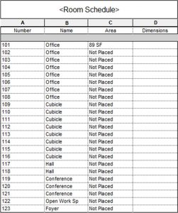
Figure 8.4 Created Room Schedule
- Go back to the Level 1 view
- Click the Architecture tab
- Click the Room icon
- On the Option Bar select the 102 Office from the drop-down menu
- Place it in the office to the right of 101 Office by clicking on the canvas
- Repeat steps 16 and 17 from left to right until all 8 office rooms are placed as shown in Figure 8.5 (Make sure the Tag on Placement is enabled)
- Place the remaining rooms as shown in Figure 8.5
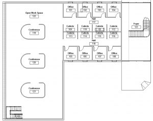
Figure 8.5 Placed rooms
Add and modify a color scheme
- Click the Annotate tab
- Click the Color Fill Legend

- Click on the white space of the canvas to place the Room Legend
- In the Space Type and Color Scheme Change the Space type to Rooms and the Color Scheme to Name the click OK
- Select the Room Legend on the canvas
- Click the Edit Scheme icon

- Change the Room colors to the following RGB values
- Conference: 185 205 182
- Cubicle: 199 233 228
- Foyer: 191 199 175
- Hall: 170 189 198
- Office: 233 226 148
- Open Workspace: 157 206 230
- Click Apply and OK
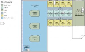
Figure 8.6 Room Legend with modified lighter colors
Add tags and color fill in section
- In the Level 1 view, click the View tab
- Click the Section tag icon

- Draw a section line across the Level 1 view from left to right as shown in Figure 8.7
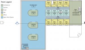
Figure 8.7 Section Line placed on the Level 1 floorplan - In the Project Browser, double-click on Section 1 to open the view
- In the Properties Palette, click the box next to Color Scheme
- In the window, change the Category to Rooms
- Select the Name
- Click Apply and OK
- Click on the Annotation tab
- Click Tag All icon

- In the Tag All Not Tagged window, click the box next to Room Tags
- Click Apply and OK
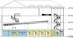
Figure 8.8 Color Scheme and Room tags applied in the Section 1 view.
